Now offering advanced Process Optimization and CEMS solutions for all major industries.
Shop By Products
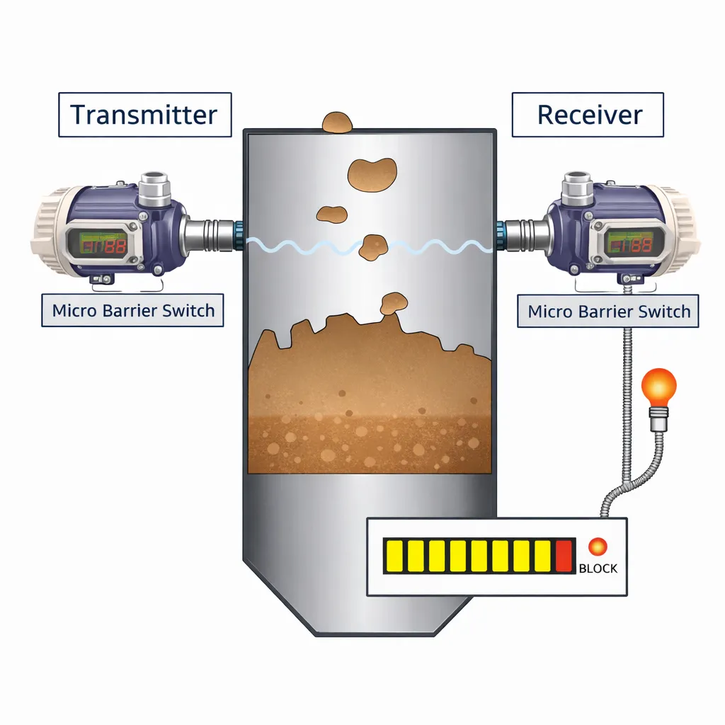

A microwave barrier level switch detects material presence by using a transmitter and receiver installed face-to-face. The transmitter sends microwave signals across the detection path. When bulk material blocks or weakens the signal, the receiver changes its relay output. As a result, plants can detect high level, low level, material flow interruption or chute blockage in suitable applications.
TIPL offers microwave-based point detection for powders, granules, bulk solids and flocculent materials. This technology suits applications where users need non-contact detection across bins, hoppers, chutes, conveyors or transfer points. In addition, it helps reduce false switching caused by mechanical wear because the detection principle does not depend on moving parts.
This technology works differently from continuous level transmitters. A radar or ultrasonic transmitter measures the changing level over a range. However, a barrier-type switch mainly confirms whether material has reached or blocked a defined point. Therefore, it is useful for alarms, interlocks, blockage detection and material presence monitoring.
| Product | Best Fit | Review Product |
|---|---|---|
| MWBS | Non-contact microwave point detection for bulk solids, storage bins, chutes, conveyors and material transfer points. | Microwave Barrier Switch |
Bulk-solid handling areas often face material buildup, chute choking, conveyor flow interruption and wrong bin-level alarms. These issues can stop material movement and disturb production. Therefore, reliable point detection helps operators respond before the blockage affects the downstream process.
For example, a microwave switch can monitor feed or discharge points, high and low alarms in storage bins, material transport on conveyors and equipment positioning. Also, it can support applications where dust, falling material or mechanical contact may challenge other switch types.
Correct selection starts with the application location. First, identify whether the switch needs to detect material level, material flow, chute blockage or equipment position. Next, check distance between transmitter and receiver, material type, dust level, temperature, pressure, mounting space and alignment possibility. After that, select the antenna, housing, power supply and installation accessories.
The transmitter and receiver should align directly across the detection path. Also, users should avoid installing them below the discharge outlet or behind beams, probes or other obstacles. If the application has high wear, high temperature, pressure or adhesive material, the installation arrangement may need a PTFE wear-resistant component or adapter.
In addition, users should check grounding and surge protection during installation. This improves electrical safety and helps protect the instrument from site disturbances.
Showing the single result
