

Quick Answer
A false or unstable radar level reading often means the transmitter is not consistently identifying the reflection from the actual product surface.
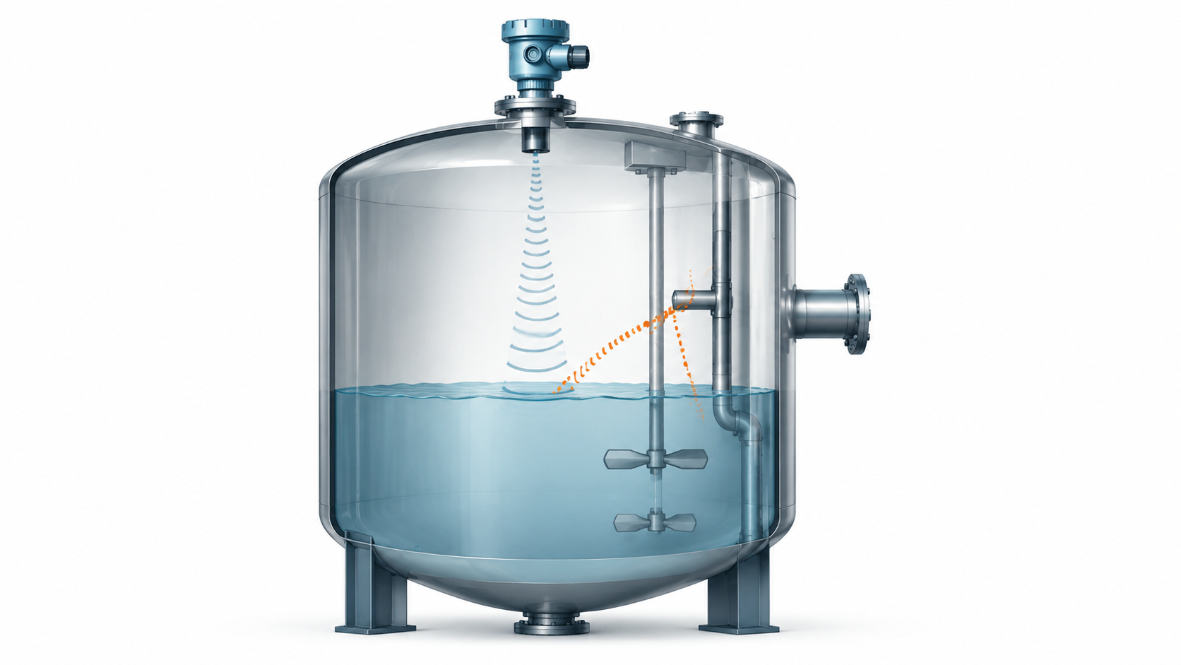
Unwanted reflections can come from vessel internals, pipes, agitators, nozzles or other structures. Process conditions such as turbulence, foam and changing surface behaviour can also change the returned signal. Incorrect installation or configuration can then make it harder for the instrument to distinguish the true level from competing echoes. [1][7]
The most useful troubleshooting sequence is therefore not to start by changing parameters. First verify the real process condition, then inspect the instrument diagnostics or echo profile, review the mounting and beam path, check the antenna and process conditions, verify configuration, and only then apply the manufacturer’s false-echo or signal-suppression functions where appropriate. VEGA, for example, describes its four fundamentals for successful radar setup as installation, application, adjustments and false-signal suppression. [2]
Scope: This guide primarily concerns non-contacting pulse and FMCW radar level transmitters. Guided-wave radar has probe-related failure modes that require a different troubleshooting path.
What Is a False Echo?
A non-contacting radar transmitter sends electromagnetic energy towards the process surface and evaluates reflected energy to determine the distance to that surface. The difficulty is that the product is not necessarily the only object capable of reflecting the radar signal. [1]
Pipes, reinforcement, agitators and other internal structures can also produce reflections. Modern instruments may use echo-processing algorithms to distinguish these unwanted signals from the true product-surface echo, but correct application and installation remain important. [1]
A useful troubleshooting distinction is therefore:
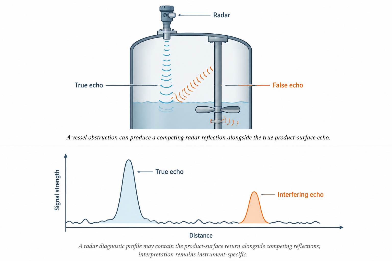
True level echo: corresponds to the actual product surface.
Interfering or false echo: comes from another reflecting object or condition and may compete with the surface echo.
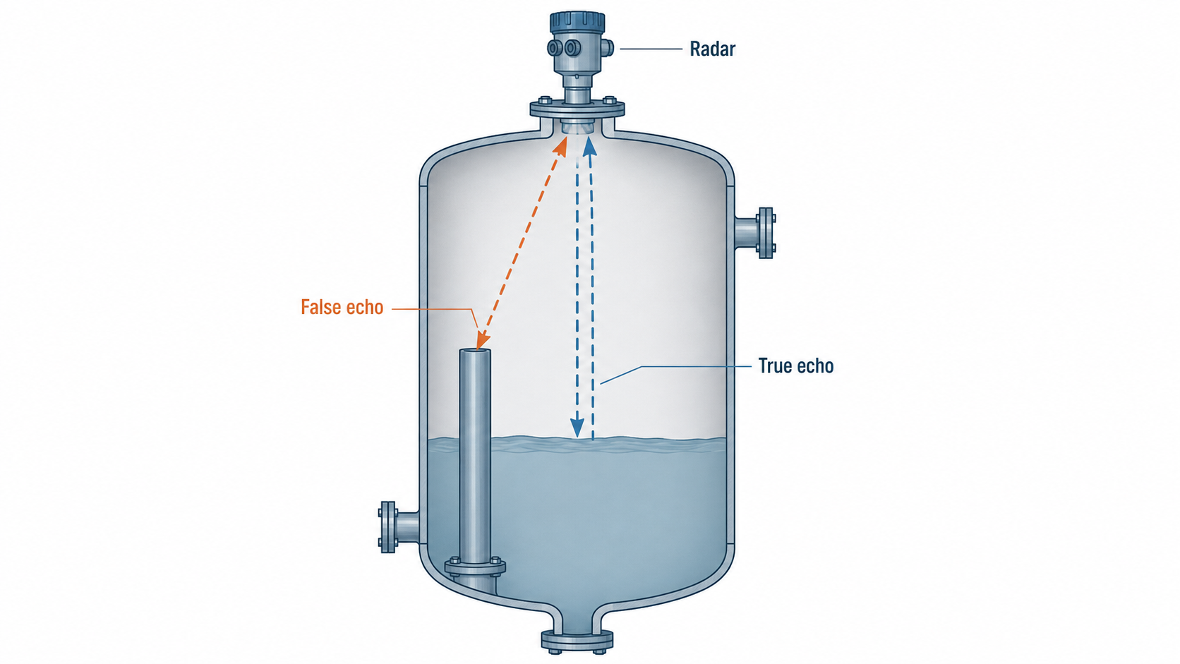
If the transmitter begins tracking the wrong echo, the displayed level can appear stuck, jump suddenly or disagree with the real vessel condition.
An Endress+Hauser application example illustrates the underlying mechanism: a non-contact radar installed on a U-seal produced multiple reflections and indicated full while the pipe was empty. Changing the radar’s orientation to obtain a stronger useful reflection resolved the application problem. [3]
What Different Symptoms Can Suggest
On mobile, swipe horizontally to view the full table →
| Symptom | Diagnostic direction |
|---|---|
| Reading stays at one incorrect level | Check for a strong fixed reflection from an internal object, nozzle or vessel geometry. |
| Reading jumps between values | Check whether the instrument is seeing competing reflections or whether the process surface is changing. |
| Reading becomes unstable when an agitator operates | Review both the agitator as a reflecting object and the resulting surface turbulence. |
| Reading becomes unreliable during foaming | Verify how the selected radar handles the particular foam and liquid properties. |
| Measurement works in one level region but becomes difficult near another | Review beam path, measurement limits, nozzle geometry and configuration. |
| Displayed percentage is consistently wrong while distance looks plausible | Check the configured 0% and 100% reference distances and output scaling. |
| Performance deteriorates after deposits form near the antenna | Inspect contamination/buildup and use the manufacturer’s signal-quality diagnostics where available. |
Engineering Note
These are diagnostic directions, not one-to-one fault diagnoses. Radar performance depends on the particular instrument and application. Emerson notes that turbulence, fluid properties, dielectric constant, surface conditions and foam can influence non-contacting radar performance, while VEGA identifies installation and application conditions as fundamental setup factors. [7][2]
Step 1: Confirm What the Process Is Actually Doing
Before altering the transmitter, establish whether the displayed problem corresponds to a real process change.
Check whether the vessel is filling or emptying, whether an agitator has started, whether foam or an unusually disturbed surface is present, and whether the process material has changed.
This matters because an unstable radar trend does not automatically mean an electronics failure. Agitation, turbulence, foam and changing media are recognized radar application conditions that can alter measurement behaviour or require different signal processing. [7]
Where an independent safe level indication is available, compare it with the radar reading. The objective is to establish whether the process is changing, the radar measurement is changing, or both.
Step 2: Look at the Radar Diagnostics Before Changing Settings
The instrument’s diagnostic information can be more useful than the displayed percentage alone.
Where the device provides an echo profile, signal-quality indication or similar diagnostic tool, review it while the problem is occurring. Siemens, for example, provides echo-profile viewing in its mobile commissioning environment, while Emerson radar products include diagnostics intended to distinguish and monitor echoes and signal condition. [4][5]
The specific display will vary by manufacturer, but useful questions include:
- Is the surface return being detected consistently?
- Are additional echoes present?
- Does an interfering echo correspond to a known tank feature?
- Does the diagnostic behaviour change when filling, agitation or another process condition changes?
- Has the signal quality changed compared with normal operation?
Step 3: Inspect the Mounting Position and Beam Path
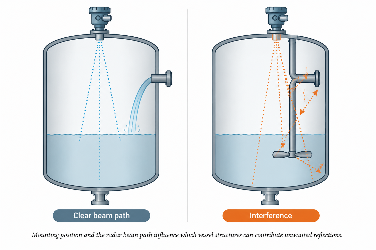
Radar installation geometry has a direct effect on what the instrument can see.
Internal pipes, agitators and other structures can produce unwanted echoes. A focused beam can reduce the likelihood that these objects enter the measurement path, but beam width and signal processing vary significantly between radar designs. [1]
Check:
- the mounting position relative to vessel walls;
- nozzle geometry;
- the direction of the beam;
- internal pipes, ladders, supports, coils or agitators;
- the filling stream;
- any modification made to the vessel after the original commissioning.
TIPL’s current radar selection guidance also identifies nozzle position, antenna clearance, tank geometry, surface behaviour and false-echo possibility as application inputs rather than afterthoughts.
If the measurement problem appeared after mechanical work inside the vessel, installation changes should be investigated before assuming the transmitter itself has failed.
Step 4: Check the Antenna and the Area Immediately Around It
Inspect the antenna and process connection according to the manufacturer’s safety and maintenance procedure.
Buildup or coating should not automatically be interpreted the same way on every radar design. Some modern radar instruments are specifically engineered to tolerate significant contamination, while other designs or application conditions may show degradation.
This is why the check should be instrument-specific. Emerson’s Rosemount 5408, for example, includes signal-quality metrics intended to alert users to potential antenna coating or buildup, while some VEGA radar products use algorithms designed to suppress interference associated with buildup. [5][8]
The correct conclusion is therefore not “buildup always causes a false reading” or “radar is unaffected by buildup.” It is to inspect the condition and apply the selected manufacturer’s guidance.
Step 5: Consider the Process Surface, Not Just the Instrument
The process can change the quality or character of the reflected radar signal.
Surface turbulence, agitation and foam can influence non-contacting radar measurement depending on the liquid properties, severity of the condition and radar design. Dielectric behaviour also affects microwave reflection. [7]
A symptom that only appears during mixing, filling or foaming should therefore be correlated with those process states.
This is particularly important before trying to remove the symptom purely through configuration. The transmitter may be revealing a genuine change in measurement conditions rather than developing an internal fault.
Step 6: Verify Configuration Against the Real Vessel
Once the physical installation and process conditions have been checked, review the configured measurement geometry.
The exact parameter names vary by manufacturer, but areas to verify can include:
- the 0% and 100% reference distances;
- vessel or measurement range;
- near-range or blocking-region settings where applicable;
- application or media selection;
- output scaling;
- any previously configured echo-processing or suppression functions.
VEGA explicitly notes that correct vessel dimensions are fundamental to radar accuracy and that its 0% and 100% points should correspond to the actual reference distances. [2]
Changing multiple configuration variables simultaneously should be avoided during diagnosis because it becomes difficult to establish which change affected the measurement.
Step 7: Use False-Echo Suppression as a Tool, Not a Substitute for Diagnosis
Radar manufacturers provide different forms of false-echo suppression, interference mapping or automated echo handling.
For example, Siemens provides Auto False Echo Suppression for its radar instruments, while VEGA includes false-signal suppression as part of its radar setup and troubleshooting methodology. Emerson’s current radar portfolio similarly uses algorithms designed to distinguish surface echoes from reflections caused by vessel obstructions. [6][2][1]
The important engineering point is that these functions are manufacturer and model specific.
Use them according to the relevant instrument manual and only after the process condition, mounting and basic configuration have been verified. A signal-processing function should not be treated as a universal cure for an unsuitable mounting position or an incorrectly configured vessel.
When Should You Reconsider the Installation or Radar Selection?
Troubleshooting sometimes shows that the transmitter is functioning correctly but the application is poorly matched to the installation.
Re-evaluation may be justified when:
- a fixed internal obstruction cannot practically be kept out of the beam;
- the existing nozzle or mounting geometry is consistently problematic;
- the process has changed materially since the instrument was selected;
- foam, surface conditions or media properties regularly make the usable reflection difficult to obtain;
- the required measurement region falls outside the practical capability of the selected configuration.
Radar technology has become capable of handling increasingly difficult installations, particularly with narrower-beam instruments and advanced echo processing. That does not make every radar interchangeable or every vessel equally easy to measure. [1][6]
For that reason, a recurring measurement problem may call for application review rather than repeated parameter adjustment.
A Practical Troubleshooting Sequence
When a radar reading is false or unstable, work through the problem in this order:
Actual process condition → radar diagnostics → mounting and beam path → antenna/process connection → process surface conditions → configuration → manufacturer-specific echo suppression.
That order reduces the risk of trying to solve an installation or process problem by changing software settings.
Key Takeaway
A false or unstable radar level reading does not automatically mean that the radar transmitter has failed.
The more useful diagnostic question is:
Is the instrument consistently identifying the true product-surface echo under the actual vessel and process conditions?
If it is not, the cause may lie in unwanted reflections, mounting geometry, process conditions, signal quality or configuration.
Only after those areas are checked should false-echo suppression or other model-specific signal-processing changes become the main corrective action.
Need to Review the Radar Application?
If troubleshooting indicates that the issue is related to beam path, vessel geometry, media behaviour, measuring range or the suitability of the selected radar principle, review TIPL’s radar level transmitter range against the actual process conditions rather than choosing a replacement on measuring range alone.
Technical References
- Emerson — Non-Contacting Radar Transmitters. Technical overview of non-contacting radar measurement, surface-echo tracking, obstructions and echo discrimination.
- VEGA — Field Service Pro Tips & FAQs. Manufacturer guidance on radar installation, application, adjustments, vessel dimensions and false-signal suppression.
- Endress+Hauser — U Seal Level Measurement Application. Manufacturer application example showing multiple reflections and the effect of changing radar orientation.
- Siemens — SITRANS mobile IQ. Device-management and diagnostic environment including echo-profile viewing for supported radar instruments.
- Emerson — Rosemount 5408 Level Transmitter. Manufacturer information on echo supervision and signal-quality diagnostics for antenna coating or buildup.
- Siemens — SITRANS LR100 Radar Level Transmitters. Manufacturer information on narrow-beam radar and Auto False Echo Suppression.
- Emerson — Guided Wave Radar Transmitters. Comparison guidance covering non-contacting radar limitations associated with obstructions, turbulence, dielectric behaviour and foam.
- VEGA — Radar Level Transmitter VEGAPULS 21 Protects Against Overfilling. Manufacturer application discussion of interfering-signal handling and sensor buildup in radar measurement.